×
- Hello
- Login or Register
- Quick Links
- Live Chat
- Track Order
- Parts Availability
- RMA
- Help Center
- Contact Us
- Shop for
- Audi Parts
My Garage
My Account
Cart
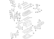
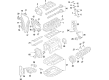
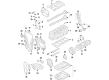
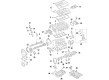
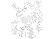
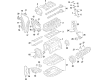
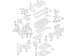
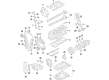
Genuine Audi Piston
Engine Pistons- Select Vehicle by Model
- Select Vehicle by VIN
Select Vehicle by Model
orMake
Model
Year
Select Vehicle by VIN
For the most accurate results, select vehicle by your VIN (Vehicle Identification Number).
83 Pistons found


Audi Piston Part Number: 06N-107-065-H
$98.88 MSRP: $138.48You Save: $39.60 (29%)Ships in 1-2 Business Days
Audi Piston Part Number: 06K-107-065-G
$171.36 MSRP: $240.00You Save: $68.64 (29%)Ships in 1-2 Business Days

Audi Piston Part Number: 06K-107-065-AS
$180.77 MSRP: $253.18You Save: $72.41 (29%)Ships in 1-2 Business Days
Audi Piston Part Number: 06D-107-066-L
$214.20 MSRP: $300.00You Save: $85.80 (29%)Ships in 1-2 Business DaysProduct Specifications- Replaces: 06D-107-066-R

Audi Piston Part Number: 06M-107-065-AB
$130.88 MSRP: $183.30You Save: $52.42 (29%)Ships in 1-2 Business DaysProduct Specifications- Replaces: 06M-107-065-AD, 06M-107-065-AK
Audi Piston Part Number: 06M-107-066-AD
$130.88 MSRP: $183.30You Save: $52.42 (29%)Ships in 1-2 Business DaysProduct Specifications- Replaced by: 06M-107-066-AB
Audi Piston Part Number: 06M-107-066-AB
$130.88 MSRP: $183.30You Save: $52.42 (29%)Ships in 1-2 Business DaysProduct Specifications- Replaces: 06M-107-066-AK
Audi Piston Part Number: 06H-107-065-DP
$456.96 MSRP: $640.00You Save: $183.04 (29%)Ships in 1-2 Business DaysAudi Piston Part Number: 06N-107-065-G
$69.02 MSRP: $96.67You Save: $27.65 (29%)Ships in 1-2 Business Days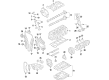
Audi Piston Part Number: 06H-107-065-AM
$83.80 MSRP: $117.36You Save: $33.56 (29%)Ships in 1-2 Business DaysProduct Specifications- Replaces: 06H-107-065-AB, 06H-107-065-AA
Audi Piston Part Number: 06K-107-065-DB
$315.34 MSRP: $441.64You Save: $126.30 (29%)Ships in 1-2 Business DaysProduct Specifications- Replaces: 06K-107-065-BM
Audi Piston Part Number: 06N-107-065-D
$117.80 MSRP: $164.98You Save: $47.18 (29%)Ships in 1-2 Business DaysProduct Specifications- Replaced by: 06N-107-065-J
Audi Piston Part Number: 06M-107-066-AK
$130.88 MSRP: $183.30You Save: $52.42 (29%)Ships in 1-2 Business DaysProduct Specifications- Replaced by: 06M-107-066-AB

Audi Piston Part Number: 06K-107-065-AB
$180.77 MSRP: $253.18You Save: $72.41 (29%)Ships in 1-2 Business Days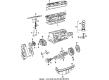
Audi Piston Part Number: 035-107-065-AC
$202.84 MSRP: $284.08You Save: $81.24 (29%)Ships in 1-2 Business DaysAudi Piston Part Number: 034-107-065-D
$202.84 MSRP: $284.08You Save: $81.24 (29%)Ships in 1-2 Business DaysAudi Piston Part Number: 054-107-065
$205.28 MSRP: $287.50You Save: $82.22 (29%)Ships in 1-2 Business Days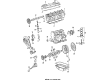
Audi Piston Part Number: 026-107-065-R
$214.20 MSRP: $300.00You Save: $85.80 (29%)Ships in 1-2 Business Days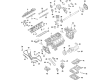
Audi Piston Part Number: 0P2-107-066-M
$227.91 MSRP: $319.20You Save: $91.29 (29%)Ships in 1-2 Business DaysProduct Specifications- Replaces: 0P2-107-066-H, 0P2-107-066
Audi Piston Part Number: 0P2-107-065-M
$227.91 MSRP: $319.20You Save: $91.29 (29%)Ships in 1-2 Business DaysProduct Specifications- Replaces: 0P2-107-065, 0P2-107-065-H
| Page 1 of 5 |Next >
1-20 of 83 Results
Audi Piston
Audi Piston turns burning fuel into the smooth rotating force that drives every Audi and is one of the reasons these cars are known for being fast yet classy. Audi has developed a loyal following blending sporty handling with practical comfort, with sedans, SUVs, and cutting-edge electric models all benefiting from the famous Quattro all-wheel drive system which grips confidently on wet or snowy roads. The brand started in 1909, expanded with Auto Union, and is now lighting the night with Virtual Cockpit displays and keen matrix headlights. Audi also pushes forward with self-driving trials and e-tron technology that is proving its focus on future mobility that remains exciting to drive. Just as the carmaker keeps changing its lineup, so does the Piston. Built of lightweight aluminum, each Piston races up and down the cylinder thousands of times per minute with tight rings sealing combustion gases and explosive pressure channeled through the connecting rod to the crankshaft. Internal oil-cooled cavities prevent heat from warping the part, while carefully shaped skirts reduce vibration so engines rev freely and last longer. Because every modern Audi has similar internal combustion principles, this Piston delivers consistent power, efficiency, and durability across the range, providing daily commutes, spirited weekend trips, and long highway cruises alike.
Stick with genuine OEM Piston when you need quality that holds up. Audi crafts these parts to hit strict factory specs for every single unit. They also run each part through rigorous checks during production to maintain high quality. You can find exact Audi Piston you need in our huge stock at AudiPartsGiant.com. You'll love our low, economical prices too. Every OEM part carries a real manufacturer's warranty, so you can buy with confidence. Returns aren't a headache here because our policy is simple. Plus, our speedy delivery gets orders out fast. Shop today and buy with total peace of mind.
Audi Piston Parts and Q&A
- Q: How to check the big-end running clearance on the piston on Audi 100?A:To test the big-end running clearance, make sure that the crankshaft is fitted in the engine. There has to be circulatory clearance between the big-end crankpin and its bearing shells. The former method consists of attaching the big-end bearing caps to the connecting rods out of the crankshaft and measuring the internal diameter of the formed big-end with internal vernier callipers and deducting the crankpin diameter to get the running clearance. The second and more precise technique involves using Plastigauge; clean all crankpins, apply a strip of Plastigauge over the crankpin journal, insert the upper big-end bearing shell, provisional reassembly of piston/connecting rod assembly, and refixing the big-end bearing caps, but not overturning the Plastigauge. Once the assembly has been dismantled, the scale on the envelope of Plastigauge can be used to measure the running clearance and compare the values with the expected values. When the clearance is very different, examine the bearing shells are of the correct size, and check that there was no dirt or oil caught when they were measured. When this is done scrape off all Plastigauge material. To install the last refitting of piston and connecting rod assemblies, the crankshaft main bearing caps should be in place, and the protective grease removed off new shells, and lubricate cylinder bores, pistons, piston rings, and upper bearing shells with clean engine oil. Beginning with piston/connecting rod assembly No 1, clamp the piston rings with compressor, and install the assembly in cylinder No 1 making sure that they fit in correctly. Push all the assembly in the cylinder, lubricate the crankpin and bearing shells and screw the big-end bearing cap in place and fit the retaining nuts/bolts finger-tight at first. Be sure that orientation of bearing cap is similar to connection rod and recesses orient the same direction as the arrow on piston crown. To certain codes of diesel engines, make sure that the piston crowns have the right orientation depending on their shape to achieve combustion attributes, and the retaining bolts/nuts are tightened to the correct torque values. When all assemblies have been refitted, hand rotate the crankshaft to make sure it moves freely. In case of new pistons or installing a new short engine, the projection of the piston crowns above the cylinder head at TDC should be measured in order to establish the type of head gasket that should be applied. To identify the type of head gasket use, use a DTI gauge to measure the highest projection at TDC of each piston, highest reading is recorded. With refitting of original pistons, it is important to use a new head gasket of similar type as that which was used initially. Lastly, reinstall the oil pump and pickup, sump and baffle plate, the flywheel and the cylinder head where necessary.
- Q: What tool is required for the piston ring compressor operation and what steps should be followed for installing the piston/connecting rod assembly on Audi A3?A:A piston ring compressor tool will be required for this operation. The running clearance check can be carried out using the original bearing shells, although using a new set is preferable for more conclusive results. Clean the backs of the bearing shells and the bearing locations in both the connecting rods and the big-end bearing caps. Press the bearing shells into their locations, ensuring that the tab on each shell engages in the notch in the connecting rod or cap, taking care not to touch any shell's bearing surface with fingers. If the original bearing shells are used, ensure they are refitted in their original locations. The running clearance can be checked, although this will be difficult without a range of internal micrometers or internal/external expanding calipers. Refit the big-end bearing cap to the connecting rod, using the marks made on removal to ensure correct orientation, with the bearing shells in place. With the original cap retaining bolts or nuts correctly tightened, measure the internal diameter of each assembled pair of bearing shells using an internal micrometer or vernier caliper. The big-end bearing running clearance is determined by subtracting the diameter of each corresponding crankshaft journal from the bearing internal diameter. The following procedure assumes that the crankshaft main bearing caps are in place. Where applicable, refit the piston cooling oil spray jets to the bottom of the cylinder block, tightening the securing bolts to the specified torque. On engines where the big-end bearing caps are secured by nuts, fit new bolts to the connecting rods by tapping the old bolts out with a soft-faced mallet and tapping the new bolts into position. Ensure that the bearing shells are correctly fitted; if new shells are being fitted, clean off all traces of protective grease with paraffin and wipe dry with a lint-free cloth. Lubricate the cylinder bores, pistons, piston rings, and upper bearing shells with clean engine oil, laying out each piston/connecting rod assembly in order on a clean work surface. Where the bearing caps are secured with nuts, pad the threaded ends of the bolts with insulating tape to prevent scratching the crankpins and bores during refitting. Start with piston/connecting rod assembly No 1, ensuring that the piston rings are spaced and clamped in position with a piston ring compressor tool. Insert the piston/connecting rod assembly into the top of cylinder No 1, lowering the big-end in first while guiding it to protect the cylinder bores. Take care not to damage oil jets located at the bottoms of the bores when guiding the connecting rods onto the crankpins. Ensure the orientation of the piston in its cylinder is correct, with markings on the piston crown, connecting rod, and big-end bearing cap pointing towards the timing belt end of the engine. On SOHC diesel engines, note that pistons 1 and 2 differ from pistons 3 and 4, with larger inlet valve chambers on pistons 1 and 2 facing the flywheel/driveplate end of the engine, while the remaining pistons face the timing belt end. New pistons have number markings on their crowns to indicate their type. On DOHC diesel engines, ensure the arrows on the piston crowns point towards the timing belt end. Using a block of wood or hammer handle against the piston crown, tap the assembly into the cylinder until flush with the top. Ensure the bearing shell is correctly installed in the connecting rod, then lubricate the crankpin and both bearing shells with clean engine oil. Taking care not to mark the cylinder bores, tap the piston/connecting rod assembly down the bore and onto the crankpin. On engines where the big-end caps are secured by nuts, remove the insulating tape from the threaded ends of the connecting rod bolts, oil the bolt threads, and on engines where the big-end caps are secured by bolts, oil the undersides of the bolt heads. Fit the big-end bearing cap, tightening its retaining nuts or bolts finger-tight at first, ensuring that the recesses machined into the connecting rod and bearing cap face the same way as the arrow on the piston crown when correctly installed. Tighten the retaining bolts or nuts to the specified torque and angle in the two stages given in the specifications. Refit the remaining piston/connecting rod assemblies in the same manner. Rotate the crankshaft by hand, checking that it turns freely; some stiffness is expected if new parts have been fitted, but there should be no binding or tight spots. On diesel engines, if new pistons or a new short engine have been fitted, measure the projection of the piston crowns above the cylinder head mating face of the cylinder block at TDC to determine the thickness of the new cylinder head gasket required. Proceed according to engine type: on SOHC petrol engines, refit the oil pump and pick-up pipe, sump, and cylinder head; on 1.6 litre DOHC petrol engines, refit the oil pick-up pipe, sump, and cylinder head; on 2.0 litre DOHC engines, refit the oil pump and pick-up pipe, sump and oil baffle plate, cylinder head, and balancer shaft assembly; on diesel engines, refit the oil pump and pick-up pipe, sump and oil baffle plate, and cylinder head.

Related Audi Parts
 Audi Camshaft
 Audi Crankshaft
 Audi Oil Filler Cap
 Audi Balance Shaft Bearing
 Audi Cam Gear
 Audi Crankshaft Timing Gear
 Audi Intake Valve
 Audi Oil Filter Gasket
 Audi Oil Pan Baffle
 Audi Spool Valve
 Audi Timing Chain Guide
 Audi Variable Timing Solenoid
Browse by Model
100 Piston 100 Quattro Piston 200 Piston 200 Quattro Piston 4000 Piston 4000 Quattro Piston 5000 Piston 5000 Quattro Piston 80 Piston 90 Piston 90 Quattro Piston A3 Piston A3 Quattro Piston A3 Sportback e-tron Piston A4 allroad Piston A4 Piston A4 Quattro Piston A5 Piston A5 Quattro Piston A5 Sportback Piston A6 allroad Piston A6 Piston A6 Quattro Piston A7 Quattro Piston A7 Sportback Piston A8 Quattro Piston allroad Piston Allroad Quattro Piston Cabriolet Piston Coupe Piston Q3 Piston Q3 Quattro Piston Q5 PHEV Piston Q5 Piston Q5 Sportback Piston Q7 Piston Q8 Piston Quattro Piston R8 Piston RS Q8 Piston RS3 Piston RS4 Piston RS5 Piston RS5 Sportback Piston RS6 Avant Piston RS7 Piston RS7 Sportback Piston S3 Piston S4 Piston S5 Piston S5 Sportback Piston S6 Piston S7 Piston S7 Sportback Piston S8 Piston SQ5 Piston SQ5 Sportback Piston SQ7 Piston SQ8 Piston TT Piston TT Quattro Piston TT RS Quattro Piston TTS Quattro Piston