×
- Hello
- Login or Register
- Quick Links
- Live Chat
- Track Order
- Parts Availability
- RMA
- Help Center
- Contact Us
- Shop for
- Audi Parts
My Garage
My Account
Cart
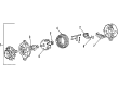
Genuine Audi 4000 Alternator
Generator- Select Vehicle by Model
- Select Vehicle by VIN
Select Vehicle by Model
orMake
Model
Year
Select Vehicle by VIN
For the most accurate results, select vehicle by your VIN (Vehicle Identification Number).
3 Alternators found

Audi 4000 Alternator Part Number: 068-903-017-PX
$408.96 MSRP: $526.00You Save: $117.04 (23%)Ships in 1-2 Business Days
Audi 4000 Alternator Part Number: 028-903-018-AX
$468.55 MSRP: $600.32You Save: $131.77 (22%)Ships in 1-2 Business Days
Audi 4000 Alternator Part Number: 068-903-017-EX
$249.90 MSRP: $323.08You Save: $73.18 (23%)Ships in 1-2 Business Days
Audi 4000 Alternator
Choose original equipment manufacturer Alternator for great performance and strong durability. They use Audi's official craftsmanship and high-grade materials, and meet strict quality standards. Are you looking for quality Alternator at a good price? Come to our online store. We carry a wide range of genuine parts for your Audi 4000 and the prices are competitive. Each part comes with the manufacturer's warranty. You can install with confidence and get steady results. Over time, you'll save money and avoid hassle. Keep your maintenance simple and protect your vehicle with OEM parts. Get the quality your 4000 needs now.
Audi 4000 Alternator Parts and Q&A
- Q: How can the voltage regulator and brushes be removed from the alternator without complete dismantling on Audi 4000?A:The voltage regulator and brushes are easily removable without removing the alternator, however the entire process of dismantling is based on the assumption that the alternator is one the bench. Begin by removing dirt on the outside of the alternator. On the Bosch models 35A, 45A, 55A, and 65A, loosen the screws to draw the voltage regulator and brushes, replacing the brushes on earlier models that were worn, and not allowing the replacement of the brushes on the later models with a hybrid regulator. These are the end housings and stator relative to each other, hold the pulley in a vice, unscrew the nut and remove the washer, pulley and fan with or without any spacers and prise out the key. Unscrew the through-bolts and drain the front housing with the rotor, and then use a mallet or puller to remove the rotor out of the front housing, and remove the spacers. Cut the screws and retainer plate out, force the bearing out of the front housing using a soft metal drift. Install a proper puller to take the bearing off the slip ring end of the rotor taking care not to damage the slip rings. Removal of lead, (after unscrewing the nut(s) on the rear housing terminal), and removal of suppressor condenser after removing the washers and insulator. Gently remove the stator and the rear housing without overstraining the three wires, and with ease, find each wire position before unsoldering with minimum heat to avoid destroying the diodes. Unscrew to disconnect diode plate with rear housing, and unscrew the wave washer. Test short to ground of stator windings with an ohmmeter or test bulb, and internal resistance between wires must be to specifications. Measure the resistance of each diode using the ohmmeter, and ensure that no resistance is found when the wires are switched. In the case of rotor windings, short to ground and internal resistance should be checked. Wipe off all parts and get new bearings and brushes when necessary. Reassembling is the opposite of dismantling, which puts bearings in proper position. In the case of Bosch model 75A and 90A, the process is the same with one exception of the fact that the diode plate has two terminals and there are two wave washers. On Motorola 35A, 55A and 65A, use a screwdriver to lift the voltage regulator taking note of wire positions before disconnection. Take out the brush holder and brushes, and replace them as a whole should they be worn out. Indicate the end housings and stator, hold the pulley, undo the nut, and remove the washer, pulley and fan with spacers and then prise out the key. Undo the through-bolts and nuts, tap off the front housing with the rotor, and loosen the screws of the retaining plate of the bearing. Take off the rotor and bearing with a mallet or puller and then take off the bearings on each end of the rotor with an appropriate puller. Take off the lid of the back housing, locate and unsolder the stator wires of the diode plate with a small amount of heat, and then remove the stator. Unsolder the D+ wire on the diode plate, marking the location of wires before screwing off the diode plate. Take out the O-ring of the rear housing and inspect the stator, diodes and rotor. Disassemble all parts and acquire new bearings and brushes when needed, lubrication of the rear housing O-ring with multi-purpose grease and then reassemble. In the case of Motorola model 45A, it is done the same with the front bearing held together by three small plates, and the cover attaching to the back housing, but the diode plate does not have a D+ wire.
- Q: What maintenance steps should be taken for the alternator to ensure the proper functioning of the electrical system on Audi 4000?A:Periodically wipe away any dirt that has accumulated on the outside of the unit and check that the plug is pushed firmly on the terminals. At the same time, check the tension of the Drive Belt and adjust it if necessary. Take extreme care when making electrical circuit connections on the car to avoid damage to the alternator or other electrical components employing semi-conductors. Always ensure that the battery leads are connected to the correct terminals. Before using electric-arc welding equipment to repair any part of the car, disconnect the battery leads and alternator multi-plug. Never run the engine with the alternator multi-plug or a battery lead disconnected.


Related Audi 4000 Parts
 Audi 4000 A/C Compressor
 Audi 4000 Crankshaft Seal
 Audi 4000 EGR Valve
 Audi 4000 Fuel Tank
 Audi 4000 Instrument Cluster
 Audi 4000 Power Steering Reservoir