×
- Hello
- Login or Register
- Quick Links
- Live Chat
- Track Order
- Parts Availability
- RMA
- Help Center
- Contact Us
- Shop for
- Audi Parts
My Garage
My Account
Cart
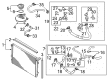
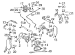
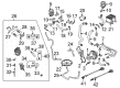
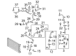
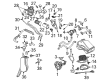
Genuine Audi TT Quattro Knock Sensor
Engine Knock Sensor- Select Vehicle by Model
- Select Vehicle by VIN
Select Vehicle by Model
orMake
Model
Year
Select Vehicle by VIN
For the most accurate results, select vehicle by your VIN (Vehicle Identification Number).
9 Knock Sensors found


Audi TT Quattro Knock Sensor Part Number: 06K-905-377-E
$101.14 MSRP: $141.65You Save: $40.51 (29%)Ships in 1-2 Business Days


Audi TT Quattro Knock Sensor Part Number: 022-905-377
$102.33 MSRP: $143.32You Save: $40.99 (29%)Ships in 1-2 Business Days


Audi TT Quattro Knock Sensor Part Number: 06E-905-377-J
$102.33 MSRP: $143.32You Save: $40.99 (29%)Ships in 1-2 Business Days


Audi TT Quattro Knock Sensor Part Number: 06F-905-377
$99.95 MSRP: $139.98You Save: $40.03 (29%)Ships in 1-2 Business Days


Audi TT Quattro Knock Sensor Part Number: 06A-905-377-B
$113.04 MSRP: $158.31You Save: $45.27 (29%)Ships in 1-2 Business Days


Audi TT Quattro Knock Sensor Part Number: 06A-905-377-C
$116.61 MSRP: $163.32You Save: $46.71 (29%)Ships in 1-2 Business Days
Audi TT Quattro Knock Sensor Part Number: 030-905-377-D
$121.37 MSRP: $169.98You Save: $48.61 (29%)Ships in 1-2 Business Days

Audi TT Quattro Knock Sensor Part Number: 06A-905-377
$71.40 MSRP: $100.00You Save: $28.60 (29%)Ships in 1-2 Business Days


Audi TT Quattro Knock Sensor Part Number: 06A-905-377-A
$80.92 MSRP: $113.33You Save: $32.41 (29%)Ships in 1-2 Business Days
Audi TT Quattro Knock Sensor
Choose original equipment manufacturer Knock Sensor for great performance and strong durability. They use Audi's official craftsmanship and high-grade materials, and meet strict quality standards. Are you looking for quality Knock Sensor at a good price? Come to our online store. We carry a wide range of genuine parts for your Audi TT Quattro and the prices are competitive. Each part comes with the manufacturer's warranty. You can install with confidence and get steady results. Over time, you'll save money and avoid hassle. Keep your maintenance simple and protect your vehicle with OEM parts. Get the quality your TT Quattro needs now.
Audi TT Quattro Knock Sensor Parts and Q&A
- Q: How must the Knock Sensor control be tested with a diagnostic scan tool on Audi TT Quattro?A:Knock sensor control must be tested using a diagnostic scan tool (VAG 1551/1552 or VAS 5051/5052). The wiring for the knock sensors can be checked for electrical short circuits. Audi identifies electrical components by a letter or a number in the electrical schematics, with these electrical identifiers listed in parentheses as an aid to electrical troubleshooting. Unplug the 3-pin harness connector for knock sensor 1, located at the right side of the cylinder head, above the engine mount. Check wiring for open or short circuit to each other, to ground, and to battery positive, with a specification of Infinity Ohms (no continuity) and a maximum wire resistance of 1.5 Ohms for signal, ground, and screening. Test for short circuits between all three terminals of the knock sensor harness connector (male side) with a specification of Infinity Ohms (no continuity); if there is continuity between any of the terminals, replace the knock sensor. Unplug the 2-pin harness connector for knock sensor 2 and check wiring for open or short circuit to each other, to ground, and to battery positive, with the same specifications. Test for short circuits between the two terminals of the knock sensor harness connector (male side) with a specification of Infinity Ohms (no continuity); if there is continuity between the terminals, replace the knock sensor. Knock sensors must be tightened to exact specification for proper operation, and the use of an accurate torque wrench is necessary when installing.

Related Audi TT Quattro Parts
 Audi TT Quattro Alternator
 Audi TT Quattro Body Control Module
 Audi TT Quattro Catalytic Converter Gasket
 Audi TT Quattro Crankshaft Position Sensor
 Audi TT Quattro Distributor Rotor
 Audi TT Quattro EGR Tube Gaskets
 Audi TT Quattro Engine Mount
 Audi TT Quattro Flywheel
 Audi TT Quattro Headlight
 Audi TT Quattro Hood Latch
 Audi TT Quattro Ignition Switch
Browse by Year
2023 Knock Sensor 2022 Knock Sensor 2021 Knock Sensor 2020 Knock Sensor 2019 Knock Sensor 2018 Knock Sensor 2017 Knock Sensor 2016 Knock Sensor 2015 Knock Sensor 2014 Knock Sensor 2013 Knock Sensor 2012 Knock Sensor 2011 Knock Sensor 2010 Knock Sensor 2009 Knock Sensor 2008 Knock Sensor 2006 Knock Sensor 2005 Knock Sensor 2004 Knock Sensor 2003 Knock Sensor 2002 Knock Sensor 2001 Knock Sensor 2000 Knock Sensor