×
- Hello
- Login or Register
- Quick Links
- Live Chat
- Track Order
- Parts Availability
- RMA
- Help Center
- Contact Us
- Shop for
- Audi Parts
My Garage
My Account
Cart
Genuine Audi 90 Idle Control Valve
IACV- Select Vehicle by Model
- Select Vehicle by VIN
Select Vehicle by Model
orMake
Model
Year
Select Vehicle by VIN
For the most accurate results, select vehicle by your VIN (Vehicle Identification Number).
2 Idle Control Valves found


Audi 90 Idle Speed Control Part Number: 034-133-455-B
$284.89 MSRP: $399.00You Save: $114.11 (29%)Ships in 1-2 Business Days

Audi 90 Idle Speed Control Part Number: 078-133-455-A
$522.41 MSRP: $731.67You Save: $209.26 (29%)Ships in 1-2 Business Days
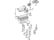
Audi 90 Idle Control Valve
Choose original equipment manufacturer Idle Control Valve for great performance and strong durability. They use Audi's official craftsmanship and high-grade materials, and meet strict quality standards. Are you looking for quality Idle Control Valve at a good price? Come to our online store. We carry a wide range of genuine parts for your Audi 90 and the prices are competitive. Each part comes with the manufacturer's warranty. You can install with confidence and get steady results. Over time, you'll save money and avoid hassle. Keep your maintenance simple and protect your vehicle with OEM parts. Get the quality your 90 needs now.
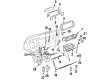
Audi 90 Idle Control Valve Parts and Q&A
- Q: How do the Idle Control Valve and Throttle Position Sensor function in relation to engine speed and air conditioning on Audi 90?A:The two-way valve I increases engine speed when it drops below 700 rpm, with the control unit located beneath the facia, while the two-way valve II activates when the air conditioner is switched on. To check valve I, lower the engine speed using the adjustment screw and ensure it increases at 700 rpm; squeezing hose 1 should cause the speed to drop. With the hose clamped, adjust the idling speed to the specified value, then unclamp the hose to verify the engine speed rises to 1050 rpm before dropping back to normal. For valve II, allow the engine to idle, squeeze the hose, and confirm no change in speed; after switching on the air conditioning, the speed should drop. To inspect the airflow meter plate, remove the air duct, disconnect the coil HT lead, and operate the starter for ten seconds, then lift the plate to check resistance across its movement range. The free travel of the plate should be 0.5 to 3.0 mm for the DZ engine and up to 2.1 mm for KV and PS engines, adjustable at the control plunger stop. For the cold start valve and thermotime switch, disconnect the HT cable from the ignition coil, then the wiring plug from the cold start valve, connecting a diode test lamp to the terminals. Disconnect the thermotime switch plug, earth the green/white wire, and operate the starter to check the test lamp lights. Refit the plug to the switch while keeping the green/white wire earthed, then remove the cold start valve to check the spray pattern, ensuring it remains dry for at least a minute. With the valve refitted and the plug disconnected, connect a diode test lamp across the terminals, operate the starter, and confirm the lamp lights for one to eight seconds based on coolant temperature. The cold acceleration enrichment activates when the thermotime switch, diaphragm pressure switch, and throttle valve switch are closed; after starting the engine and letting it idle, the test lamp should not light, but it should briefly light when the throttle is quickly opened. For the diaphragm pressure switch, disconnect the wiring, run the engine at idle, and check resistance with an ohmmeter, ensuring it reads infinity. Opening the throttle should cause a brief drop in resistance. For the throttle valve switch, disconnect the wiring plug, connect an ohmmeter, and confirm infinity resistance with the throttle closed; slowly opening the throttle should register infinity resistance until the switch contacts close, with the gap between the idling stop and throttle lever set between 0.2 and 0.6 mm. For the auxiliary air valve, disconnect the HT lead, connect a diode test lamp across the plug terminals, and operate the starter to check the lamp lights. After reconnecting the HT lead, start the engine, squeeze the hose between the auxiliary air valve and inlet manifold, and ensure the engine speed drops. Reconnect the wiring plug and repeat the test with the engine warm, confirming no change in speed. For the warm-up valve, disconnect the HT lead, connect a diode test lamp across the plug terminals, and operate the starter to check the lamp lights. The basic throttle valve setting is typically factory-set and should not require adjustment; if disturbed, loosen the nut, unscrew the adjusting screw to create a gap, turn it clockwise until it just touches the stop, then turn it an additional half-turn, applying locking fluid to the nut threads before tightening while holding the screw stationary, and check the idling settings after adjustment.


