×
- Hello
- Login or Register
- Quick Links
- Live Chat
- Track Order
- Parts Availability
- RMA
- Help Center
- Contact Us
- Shop for
- Audi Parts
My Garage
My Account
Cart
Genuine Audi 80 Driveshaft
Drive Shaft- Select Vehicle by Model
- Select Vehicle by VIN
Select Vehicle by Model
orMake
Model
Year
Select Vehicle by VIN
For the most accurate results, select vehicle by your VIN (Vehicle Identification Number).
2 Driveshafts found

Audi 80 Drive Shaft Part Number: 8A0-521-101-B
$696.15 MSRP: $900.00You Save: $203.85 (23%)Ships in 1-2 Business DaysAudi 80 Drive Shaft Part Number: 893-521-101-X
$1408.33 MSRP: $1685.00You Save: $276.67 (17%)Ships in 1-2 Business Days
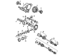
Audi 80 Driveshaft
Choose original equipment manufacturer Driveshaft for great performance and strong durability. They use Audi's official craftsmanship and high-grade materials, and meet strict quality standards. Are you looking for quality Driveshaft at a good price? Come to our online store. We carry a wide range of genuine parts for your Audi 80 and the prices are competitive. Each part comes with the manufacturer's warranty. You can install with confidence and get steady results. Over time, you'll save money and avoid hassle. Keep your maintenance simple and protect your vehicle with OEM parts. Get the quality your 80 needs now.
Audi 80 Driveshaft Parts and Q&A
- Q: How to properly remove and refit a driveshaft on Audi 80?A:Apply the handbrake and prise the trim from the relevant front wheel. Loosen the driveshaft nut or bolt with the weight of the car still on the wheels, as it is tightened to a very high torque and should not be loosened with the car raised. Loosen the wheel bolts, then jack up the front of the car and support it on axle stands before removing the wheel. Remove the driveshaft nut and washer or bolt as appropriate, then unbolt and remove the driveshaft lower cover from the gearbox if fitted. Working beneath the car, unscrew and remove the bolts securing the inner constant velocity joint to the gearbox drive flange, noting the location of the bolt plates. Support the inner end of the driveshaft or temporarily tie it to one side, and recover the gasket if fitted. For models with integral strut and wheel bearing housing up to chassis number F89J373598, mark the lower suspension balljoint arm in relation to the suspension wishbone on manual steering models, unscrew the nuts, and release the balljoint arm. On power steering models, disconnect the front anti-roll bar link from the anti-roll bar by unscrewing the nut, then unscrew and remove the wishbone pivot bolts and swivel the wishbone downwards. Use a hub puller to remove the driveshaft from the front wheel hub and withdraw it from under the car. If it is necessary to move the car on its wheels before refitting the driveshaft, clamp the wheel bearing inner tracks together using a long bolt and washers to prevent damage. Clean the splines on the outer end of the driveshaft and inside the hub thoroughly, removing all traces of old locking fluid. Apply a 5.0 mm band of locking fluid to the outer end of the driveshaft splines, then insert the driveshaft in the hub. On power steering models, align the wishbone holes and insert the pivot bolts, but do not fully tighten them until the weight of the car is on the wheels. Reconnect the anti-roll bar link and tighten the nut. For manual steering models, refit the balljoint arm to the wishbone, using water pump pliers to pull the arm into its previously noted position before tightening the nuts, taking care not to trap the balljoint rubber dust cover. For models with separate strut and wheel bearing housing from chassis number F89J373599 onwards, turn the steering to full lock, pull the driveshaft out of the front wheel hub, and withdraw it from under the car, pulling back the speed sensor slightly on models with ABS. If it is necessary to move the car on its wheels before refitting the driveshaft, clamp the wheel bearing inner tracks together using a long bolt and washers to prevent damage, and clean the splines on the outer end of the driveshaft and inside the hub thoroughly. With the steering on full lock, insert the driveshaft in the hub, pushing the speed sensor fully in on models with ABS. Where applicable, locate a new gasket on the inner end of the driveshaft after cleaning the seat, removing the backing foil if the gasket has its own adhesive. Position the driveshaft on the gearbox drive flange, insert the bolts and plates, and tighten to the specified torque. Refit the driveshaft lower cover if fitted. If a driveshaft nut is fitted, apply locking fluid to its threads, refit it with the washer, and tighten moderately. If a driveshaft bolt is fitted, use a new bolt and tighten moderately. Refit the wheel and tighten the bolts moderately before lowering the car to the ground. Fully tighten the driveshaft nut or bolt and the wheel bolts to the specified torques, ensuring that if a bolt is fitted, it is tightened to the specified torque and then angle-tightened. Where applicable, also tighten the wishbone pivot bolts and refit the wheel trim. Allow any locking fluid used to harden before using the car on the road.
- Q: How to mount and reassemble a driveshaft with constant velocity joints on Audi 80?A:Mount the driveshaft in a vice and, using a suitable drift, drive the cap from the inner constant velocity joint while pulling the rubber bellows towards the middle of the driveshaft. Remove the circlip from the inner end of the driveshaft, support the inner constant velocity joint in a vice, and press or drive through the driveshaft. If fitted, remove the dished washer from the end of the driveshaft, noting its location, then pull off the inner rubber bellows. Remove the clips from the outer rubber bellows, cutting free any crimped types, and detach the bellows from the outer constant velocity joint, pulling towards the middle of the driveshaft. Strike the outer constant velocity joint at the indicated point to release the joint hub from the circlip on the driveshaft, then remove the joint. Take off the circlip, spacer, and dished washer from the end of the driveshaft, noting their locations, and pull off the outer rubber bellows. Clean all components and examine them for wear, damage, and deterioration; each joint is available separately as a kit containing rubber bellows, joint, washers, grease, and, if applicable, the driveshaft nut/bolt, clips, and inner bolts. Renew both retaining circlips as a matter of course and avoid dismantling the joints if intending to re-use them. Begin reassembly by smearing a little grease on the small inner ends of the bellows, then locate both on the driveshaft towards the middle. Position the dished washer, spacer, and circlip on the outer end of the driveshaft, ensuring the circlip can move freely in its groove and the convex side of the dished washer faces the end of the driveshaft. Slide the outer constant velocity joint onto the driveshaft and drive on the hub using metal tubing until the circlip engages. Fill the outer joint with the specified amount of grease, working it well into both sides of the joint. Slide the outer bellows onto the constant velocity joint, locating the small diameter end in the driveshaft groove, and temporarily lift the bellows with a screwdriver to release any vacuum that may have formed before fitting and tightening new clips. Fit the dished washer on the inner end of the driveshaft with its convex side towards the end; note that models with KV, NG, and 7A engines may not have this washer. If fitted, ensure the correct version is used, then slide the inner constant velocity joint onto the driveshaft with the chamfer on the hub against the shoulder or dished washer, fully driving on the hub using metal tubing before fitting the retaining circlip in its groove. Fill the inner joint with the specified amount of grease, working it well into both sides of the joint. Finally, apply some sealant to the surface of the cap that contacts the joint, slide the rubber bellows into position, and locate the small diameter end in the driveshaft groove, lightly tapping the cap onto the joint.


